
Vertical-roll mills are essential steelmaking equipment used to roll billets to the required shape and dimensions. Mill stands with vertical rolls share three features: properly designed rolls, a rigid stand structure, and an efficient drive. Their vertical-roll bearings consequently show similar early-failure modes. Because these bearings have the highest failure frequency among bearings on an H-beam hot-rolling line and significantly affect production, this article examines the vertical-roll bearings on a German SMS Meer TM large H-beam universal reversing mill at a Chinese steel producer, analyzes causes of early failure, and proposes improvements.
Vertical Rolls and Their Bearings
The large H-beam line comprises four stands: one two-high reversing breakdown mill (BD) and one universal tandem group. The tandem stands are arranged UR-E-UF: a universal roughing mill, an edging mill, and a universal finishing mill in continuous sequence.
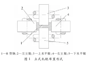
The line has four vertical rolls installed in the universal roughing mill (UR) and universal finishing mill (UF). The roll arrangement is shown in Figure 1.
Each vertical roll weighs 10-17 tonnes. It is driven by contact with the workpiece, with a theoretical maximum speed of 10 m/s and a maximum load of approximately 6,000 kN. Water cooling keeps rolling temperature generally below 40°C. The bearings use oil-air lubrication with ISO VG 460 gear oil.
Usable vertical-roll diameter ranges from 880 to 980 mm. After rolling approximately 3,000 tonnes, each roll is removed and turned by an amount determined by wear. Each bearing is fitted with one roll ring; when the ring is scrapped, the complete vertical roll is retired. Rolling schedules and pass counts vary with H-beam size. A beam generally undergoes five to nine reversing passes completed within three to five minutes.
The roll-ring bore has an interference fit with the bearing outside diameter, with 0.075-0.122 mm interference. The bearing inner ring has a transition fit on the vertical-roll mandrel, ranging from 0.060 mm maximum clearance to 0.025 mm maximum interference.
Bearing Failure Modes and Causes
The principal early-failure mode of the vertical-roll bearing shown in Figure 2 is seizure. Typical evidence includes severe cage wear with debris filling the space between rollers and raceways, and fractured cage bars that allow rollers to crowd together and slide on the raceway.
Analysis indicates that impact forces during operation cause the failures. These impacts arise from two sources.
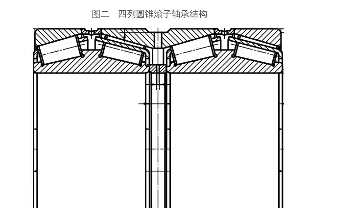
(1) Impact at the start of rolling. During biting, rolling, and release, the raceways and rollers are in normal contact. Between workpieces, the heavy vertical roll settles under its own weight and contact becomes abnormal. When rolling starts, contact changes instantly from abnormal to normal. Because operating clearance and other gaps are present—including axial gaps among rollers, the inner raceway, and cage pockets, and radial cage movement after assembly shrinkage—the rollers strike the cage and inner-ring ribs. Larger clearances produce greater impact.
(2) Inertial impact during the transition between biting and release. During reversing rolling, the vertical-roll bearing operates at 190 r/min. The roll reverses direction almost instantaneously at each transition, producing very high inertial impact between rollers and cage pockets.
Because rollers and cages differ greatly in hardness, these impacts—especially reversal inertia—repeatedly plastically deform the cage bars until they fracture. High contact stress between cage-pocket and roller surfaces also causes severe pocket wear, filling the rolling contacts with debris.
Main Improvement Measures
3.1 Increase Cage Strength
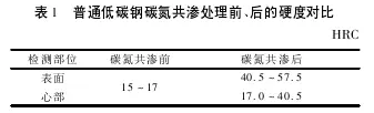
Carbonitriding the cage increases both surface and core hardness. Table 1 compares ordinary low-carbon steel before and after treatment. Carbonitriding substantially raises both values to levels broadly equivalent to the surface and core hardness of No. 40 steel after surface hardening.
3.2 Reduce Impact During Bearing Operation
(1) Machine the cage bottom and edges to reduce mass and therefore inertial impact.
(2) Reduce axial gaps among rollers, cage pockets, and the inner raceway. Keeping roller length unchanged, slightly expand the cage to shorten its pockets. For a 380690 non-standard vertical-roll bearing, this process shortened the pocket by 0.3 mm, while the specified inner-ring raceway width was reduced by 0.5 mm.
(3) Reduce axial bearing clearance. For the 380690 bearing, clearance was reduced from 0.7-0.8 mm to 0.45-0.55 mm.
(4) Reduce radial cage movement created by pocket-slope pressing. For the 380690 bearing, the radial coordinate of the pressed slope was reduced from one-half to one-third of cage plate thickness.
(5) Reduce radial movement after the cage is contracted during assembly. For the 380690 bearing, this movement was reduced from more than 0.8 mm to less than 0.5 mm.
Results
After these measures were implemented, annual seizure frequency of vertical-roll bearings on one Chinese steel producer's large H-beam line fell from 8% to below 1%. Average service life increased to more than 195 hours, 11.43% above the imported bearings previously used. On another medium H-beam line, no seizure occurred for two years; minimum bearing life reached a throughput of 5 × 10⁴ tonnes, matching imported products. Imported bearings were fully replaced. The same experience was successfully extended to roughing stands on hot-strip lines, vertical-roll bearings on certain medium- and heavy-plate mills, and stamped-cage four-row tapered roller bearings supporting rolls on single-stand reversing cold-strip mills.