
Angular contact ball bearings are widely used because they combine excellent speed capability with high load capacity. Compared with deep-groove ball bearings, they provide not only strong radial-load capacity but also excellent axial-load capacity. Their particular geometry, however, means that a single bearing can carry axial load in only one direction, which imposes specific application requirements.
Geometry and Unidirectional Load Capacity — Consider the internal geometry of an angular contact ball bearing shown below:
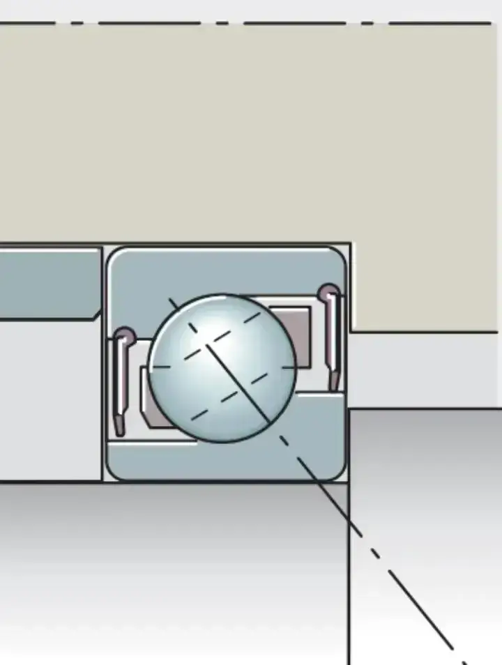
As illustrated, the internal geometry permits axial load in only one direction: from the thick shoulder of the inner ring toward the thick shoulder of the outer ring. An axial load in the opposite direction tends to separate or actually disengage the bearing. The rolling elements can then no longer roll correctly, causing heat and wear and ultimately premature bearing failure.
Why Axial Preload Is Necessary — To prevent this failure mode, an angular contact ball bearing must not be exposed to axial force opposite its load-carrying direction. The solution is to apply axial preload.
Preloading a Single Bearing — For a single angular contact ball bearing, preload must be applied in its axial load-carrying direction, shown in the figure as the direction from the thick shoulder of the outer ring toward the thick shoulder of the inner ring.
Determining Preload — The primary purpose of preload is to counter any reverse axial load. The preload must therefore exceed the maximum expected reverse axial load. Even under that maximum reverse load, the internal bearing load must still satisfy the specified minimum-load requirement. In general, the preload equals the maximum reverse axial load plus the bearing's minimum required load, with other site-specific factors also considered.
Paired Angular Contact Ball Bearings (Face-to-Face or Back-to-Back) — Two single-row angular contact ball bearings are commonly paired to accommodate bidirectional axial loads. Both face-to-face and back-to-back arrangements place the bearings' axial load directions opposite one another:
Back-to-back (DB): the thick shoulders of the outer rings face each other.
Face-to-face (DF): the thin shoulders of the outer rings face each other. In either arrangement, each bearing carries axial load in one direction, as shown below for a back-to-back pair:
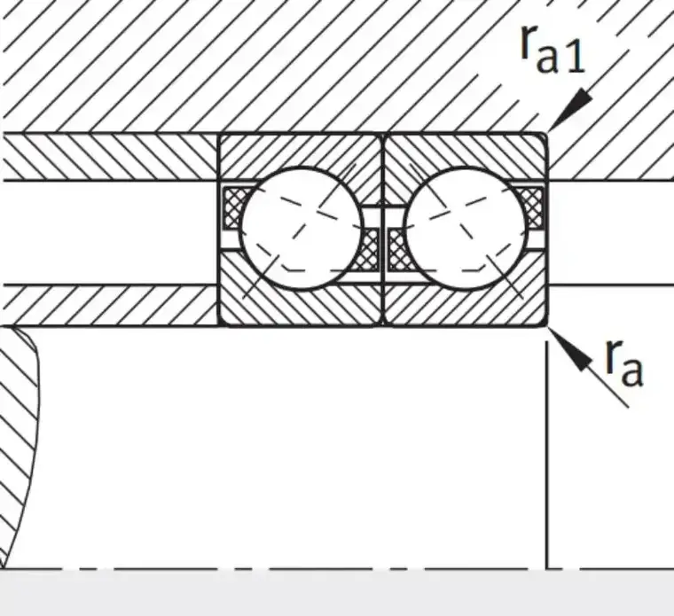
In the figure, the left bearing carries axial load toward the right, while the right bearing carries axial load toward the left. Axial load in either direction is therefore supported by one of the bearings. External axial force is usually not required merely to establish preload, although this does not mean that a paired set cannot be preloaded.
Applying Preload to a Paired Set
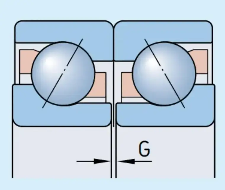
In the back-to-back pair shown above, the end faces at the thick and thin shoulders may not lie in the same plane when the angular contact bearings are at zero clearance. In the illustrated case, the thick shoulder stands higher than the thin shoulder. When the thick shoulders are clamped together, a gap remains between the thin shoulders. Applying external force to close this gap produces negative internal clearance and therefore preload.
Controlling Preload — In manufacture and application, the dimensions of the thin and thick shoulder faces are precisely controlled and matched to manage internal preload or initial clearance after pairing. Besides direct DB or DF mounting, another common arrangement locates two angular contact ball bearings at opposite ends of a shaft, as shown below:
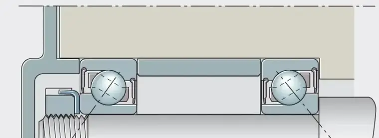
In the figure, two bearings in a back-to-back arrangement are located at opposite ends of the shaft and separated by spacers. Internal clearance or preload is controlled by spacer length: a longer spacer produces greater preload, while a shorter spacer produces less.
Other Factors Affecting Preload and Clearance — In a paired arrangement, the interference fit between the inner rings and shaft can also be adjusted to influence internal clearance. The reduction in clearance caused by fit will be discussed separately. In summary, the final operating clearance of an installed pair under stable conditions is determined by the combined effects of:
Externally controlled face dimensions, established by matching or spacer length.
The fit between the bearing inner rings and the shaft.
Clearance reduction caused by temperature changes. Final preload must ensure that, under axial load in either direction, the unloaded bearing does not separate and its internal load always remains above the minimum-load requirement.
Application Differences — Industrial motors often use factory-matched angular contact bearing sets, eliminating on-site matching calculations and adjustment. In gearboxes and similar applications, however, accurate preload calculation and adjustment are generally essential.