Miniature Thrust Ball Bearings
Compact single-direction thrust ball bearings for precise axial support in miniature mechanisms and space-limited assemblies.
Bore range: 2-10 mm
Load direction: Single direction
Miniature Thrust Ball Bearings Overview
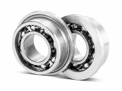
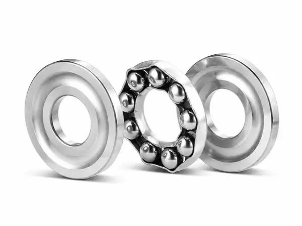
Miniature thrust ball bearings are compact, separable bearings designed primarily to carry axial loads in one direction. A ball-and-cage assembly operates between two bearing rings, providing low-friction axial support where radial space, axial height and component weight are tightly controlled.
The product range comprises the FM series with raceway and the F series without raceway. Bore diameters range from 2 mm to 10 mm, outside diameters from 6 mm to 20 mm and overall heights from 3 mm to 7 mm. FM models include reference grease and oil speed ratings, while F-series specifications cover dimensions, load ratings, cage type, ball complement and reference weight.
Key Features
- Designed for axial load support in one direction; radial load should be carried by a separate bearing arrangement.
- Compact outside diameter and low overall height suit miniature mechanisms and space-limited assemblies.
- Separable rings and ball-and-cage assembly simplify installation, inspection and lubrication.
- FM series with raceway provides formed running surfaces for controlled ball guidance and axial load distribution.
- F series without raceway offers a simple compact configuration for light-duty axial support.
- FM-series models use TP cages, while F-series models use TD cages.
Design Variants
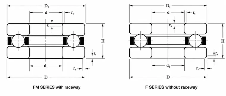
FM series with raceway and F series without raceway
FM series with raceway: Twelve models with 3-10 mm bore diameters, TP cages and reference speeds for grease and oil lubrication.
F series without raceway: Eleven models with 2-10 mm bore diameters and TD cages, intended for compact light-duty axial arrangements.
Stainless option: Stainless-material bearings may be identified with suffix H; availability should be confirmed before ordering.
Suffix and Configuration Guide
| Configuration | Typical designation | Meaning |
|---|---|---|
| With-raceway series | F6-14M | Suffix M identifies the FM series with raceway |
| Without-raceway series | F7-15 | F designation without M identifies the without-raceway series |
| Stainless option | Suffix H | Stainless material may be identified with suffix H |
Available specifications depend on subseries, bearing size, material, cage and application. The following capability range supports preliminary selection; final values should be confirmed for the selected designation.
| Parameter | Series capability |
|---|---|
| Dimensional range | Bore d 2-10 mm; outside diameter D 6-20 mm; height H 3-7 mm |
| Product series | FM series with raceway and F series without raceway |
| Load direction | Single-direction axial load |
| Load-rating range | Basic dynamic axial load Ca 117-3,939 N; basic static axial load C0a 83-3,571 N |
| FM reference speed | Grease 8,000-19,000 r/min; oil 13,000-28,000 r/min |
| Cage type | FM series: TP; F series: TD |
| Ball complement | 6-10 balls; ball diameter 1.000-3.175 mm |
| Reference weight | Approximately 0.6-9.9 g across the product range |
Applications & Selection
Typical Applications
- Miniature electric motors, actuators and compact drive mechanisms
- Precision instruments, measuring devices and optical equipment
- Printers, scanners, office equipment and paper-handling mechanisms
- Small gearboxes, lead-screw supports and axial positioning mechanisms
- Medical and laboratory equipment with low axial loads and limited space
- Compact automation, robotics and light-duty rotating assemblies
Selection Notes
- Use these bearings for axial load in one direction and provide a separate bearing arrangement for radial loads.
- If axial loads act in both directions, use two bearings in an appropriate opposed arrangement and confirm preload or end play.
- Confirm whether the application requires the FM with-raceway design or the simpler F without-raceway design.
- Check d, D, d1, D1 and H against the shaft, housing and axial locating shoulders before finalizing the model.
- Use the specified speed values as reference data and apply suitable reductions for load, temperature, lubrication and mounting conditions.
- For stainless versions, confirm the stainless grade, suffix H, cage material and lubricant compatibility with the operating environment.
Ordering Information
For quotation and technical confirmation, please provide the bearing designation or dimensions (d x D x d1 x D1 x H), quantity, FM or F design requirement, material, cage requirement, lubricant, operating speed, temperature range, axial load magnitude and load direction.