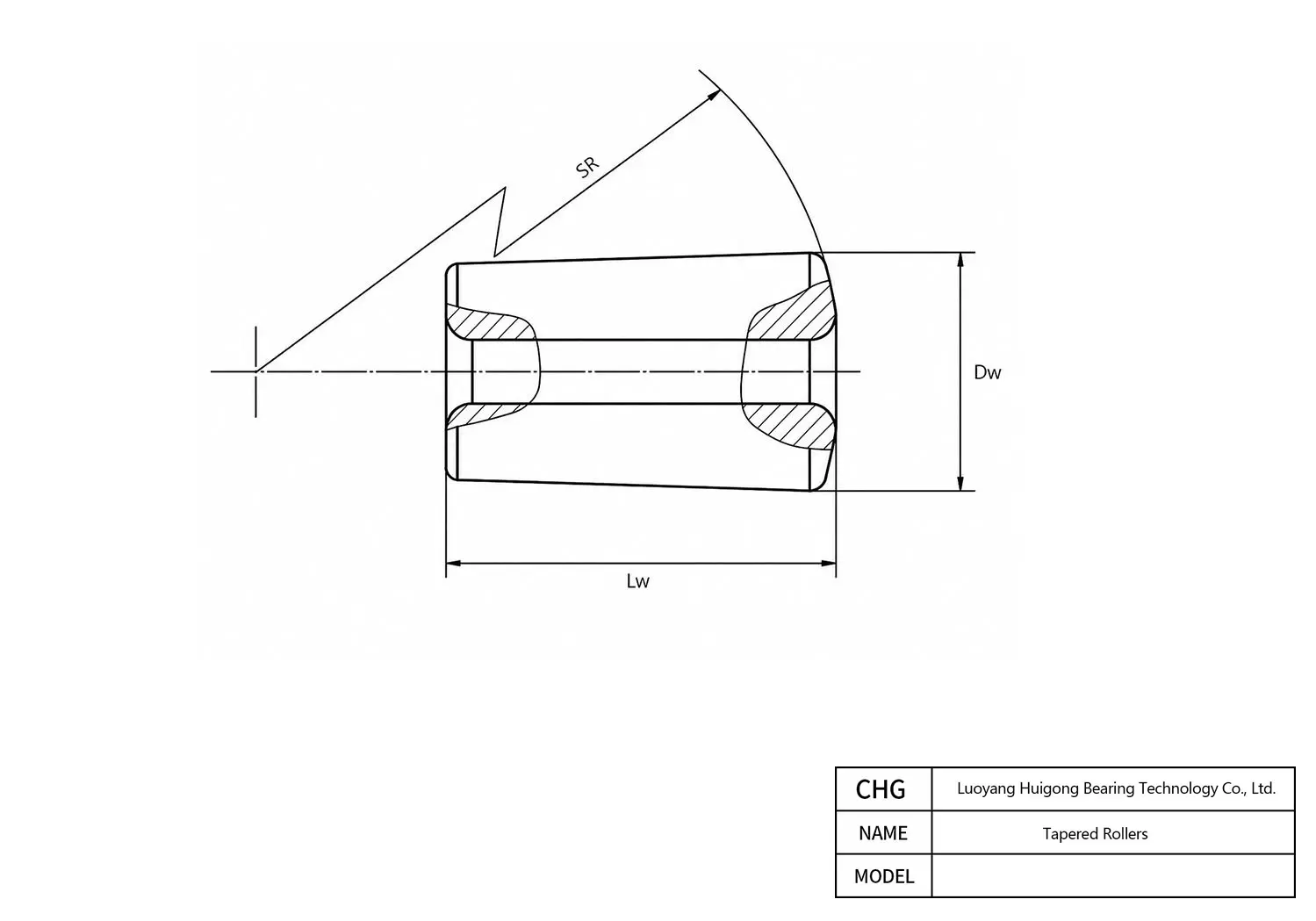
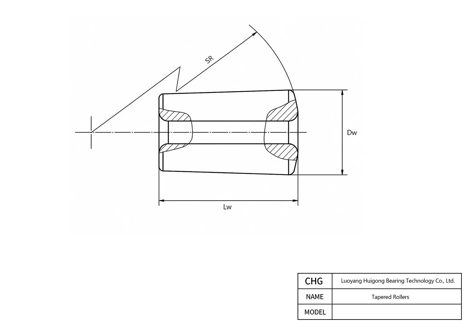
Manufactured by CHG Bearing, the 64*78.32 is a precision Tapered Rollers. Key dimensional parameters include a mm bore diameter, a mm outer diameter, and a mm overall width. This component is designed to meet standard load requirements and ensure consistent operational performance. For comprehensive technical evaluation, please explore the detailed specifications, dimensional data, product images, and CAD drawings provided below. A complete PDF data sheet is also readily available for direct download to support your engineering and procurement needs.
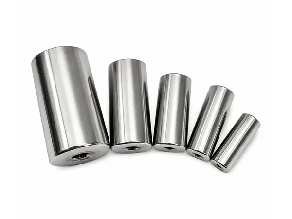
64*78.32 - Tapered Rollers
Technical Specifications
| Overview | |
|---|---|
| Part Number | 64*78.32 |
| Brand | CHG® |
| Product Type | Tapered Roller |
| Taper Angle | 1°9' |
| Dimensions | |
| Roller Length, Lw | 78.32 mm |
| Center Recess Diameter | 32 mm |
| Through-hole Diameter | - mm |
| Center Recess Depth | 2 mm |
| Large-end Diameter, Dw | 64 mm |
| Spherical End Radius, SR | 1371 mm |
| Through-hole Chamfer | - mm |
| Large-end Diameter Tolerance | -0.015 to +0.03 mm |
| Through-hole Coaxiality | - mm |
| Rolling Surface Roughness, Ra (µm) | 0.25 |
| Axial Chamfer — Large End | 1.5 mm |
| Axial Chamfer Tolerance — Large End | -0.5 to +0.5 mm |
| Radial Chamfer — Large End | 1.2 mm |
| Radial Chamfer Tolerance — Large End | -0.4 to +0.4 mm |
| Axial Chamfer — Small End | 1.2 mm |
| Axial Chamfer Tolerance — Small End | -0.4 to +0.4 mm |
| Radial Chamfer — Small End | 1.5 mm |
| Radial Chamfer Tolerance — Small End | -0.5 to +0.5 mm |
| Performance | |
| Spherical End Surface Roughness, Ra (µm) | 0.4 µm |
| Dimensional & Geometrical Accuracy | |
| Roller Length Tolerance | -0.5 to 0 mm |
| End-face Runout | - mm |
| Diameter Variation Between Ends | ±0.004 mm |
| Roundness | 0.004 mm |
| Ovality | 0.004 mm |
 64*78.32 64 mm 78.32 mm 1371 mm
 Frequently Asked Questions about 64*78.32 Tapered Rollers
Find key technical answers regarding dimensions, specifications, and replacement options for this model.
When fitting 64*78.32 over a mm shaft, CHG Bearing strictly recommends uniform induction heating (controlled between 90°C and 110°C) or precision hydraulic press sleeves. Under no circumstances should direct impact blows be struck against the rings or cage, as shock loads cause brinelling indents and premature spalling.
Each 64*78.32 produced in CHG Bearing manufacturing facilities features accurately profiled corner chamfers complying with DIN 5412 / ISO standard corner radii. When designing mating shafts and housing shoulders, machining an undercut or fillet radius strictly within the inner ring clearance limit ( mm bore side) ensures perfect planar contact without edge binding.
Engineered according to international ISO boundary plans, CHG Bearing supplies 64*78.32 with a precision bore diameter (d) of mm, an outside diameter (D) of mm, and a nominal ring width (B) of mm. This configuration yields an effective cross-sectional wall thickness of 0 mm and an envelope ratio (D/d) of 0, delivering compact rigidity for OEM machinery housings.
As a primary manufacturer, CHG Bearing supports both trial batch evaluations and container-load supply for 64*78.32. Standard catalog sizes are stocked for rapid 3–7 day dispatch, while high-volume OEM production runs typically dispatch within 30–45 days.