Thrust Ball Bearings
Single- and Double-Direction Designs for Axial Load SupportBearing Type: Thrust Ball Bearing
Design Range: Single-direction, double-direction and angular-contact thrust designs
Main Series: 50000 Type (8000 Series); 52000 Type (38000 Series)
Primary Load: Axial load only; radial load is not permitted
Axial Direction: One direction or two directions according to design.
Technical Specifications
| Specification | Details |
|---|---|
| Bearing Type | Thrust Ball Bearing |
| Design Range | Single-direction, double-direction and angular-contact thrust designs |
| Main Series | 50000 Type (8000 Series); 52000 Type (38000 Series) |
| Primary Load | Axial load only; radial load is not permitted |
| Axial Direction | One direction or two directions according to design |
| Size Coverage | Catalog data supplied for d 140-1600 mm |
| Cage | Pressed steel; machined solid cage for larger sizes |
| Speed | Standard thrust types: moderate or low speed; angular-contact types: higher speed |
| Alignment | Shaft and housing axes must remain concentric and support faces perpendicular |
| High-Precision Option | SP/P4 rotational accuracy for double-direction angular-contact designs |
| Lubrication | Grease or oil according to speed and load |
Thrust Ball Bearings Overview
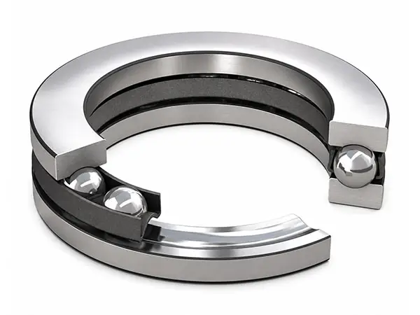
A single-direction thrust ball bearing consists of one row of balls with a cage, one shaft washer and one housing washer. It supports axial load in one direction only and cannot carry radial load. The separable components simplify mounting and inspection.
A double-direction thrust ball bearing uses two ball rows, one central shaft washer and two housing washers to support axial loads in both directions. Angular-contact thrust versions provide greater stiffness and higher-speed capability for machine-tool and precision spindle positions.
Axial Load Capacity and Directional Location
The washer and ball-raceway geometry transmits thrust directly along the bearing axis. Select single-direction designs for one-way axial location and double-direction designs when shaft location is required in both axial directions.
- Axial load only
- Single-direction axial location
- Double-direction axial support
- Separable construction
Alignment, Cage and Speed Characteristics
Correct alignment is essential because thrust ball bearings do not compensate for shaft inclination or housing distortion. Standard designs generally use pressed steel cages; bearings with larger outside diameters may use machined solid cages. Double-direction angular-contact designs are selected when higher speed, stiffness and precision are required.
- Accurate coaxial mounting
- Pressed or machined cage options
- Higher-speed angular-contact designs
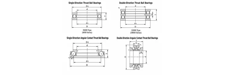
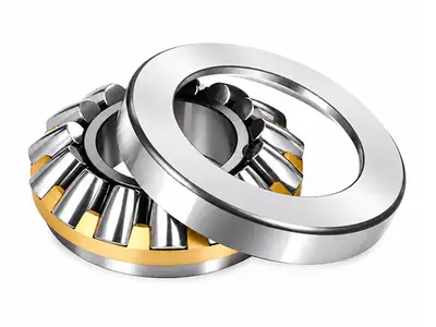
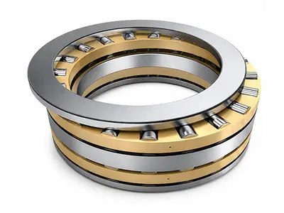
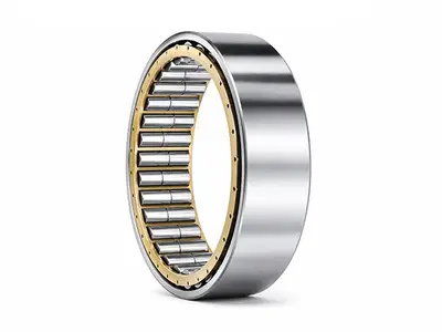
Single-/double-direction and angular-contact thrust ball bearing structures
Single-/double-direction and angular-contact thrust ball bearing structures
| Type | Series | Function |
|---|---|---|
| Single-Direction | 50000 Type (8000 Series) | Axial load and location in one direction |
| Double-Direction | 52000 Type (38000 Series) | Axial load and location in two directions |
| Single-Direction Angular Contact | 569/561 Series | Higher stiffness and speed in one direction |
| Double-Direction Angular Contact | 234 Series | High-precision bidirectional spindle support |
Mounting and Operating Considerations
Keep shaft and housing bore axes concentric and support faces perpendicular to the bearing axis. For standard single-direction designs, provide approximately 0.5-1 mm radial clearance between the housing washer outside diameter and housing bore. Verify axial direction, cage, lubrication, temperature rise and limiting speed before continuous operation.
Catalog bore range: 140-1600 mm
Typical Applications
- Rolling-mill axial locating positions
- Machine-tool spindles
- Precision spindle assemblies
- Gearboxes and vertical drives
- Industrial equipment with one-way thrust
- Bidirectional thrust support systems