Crossed Roller Slewing Bearings
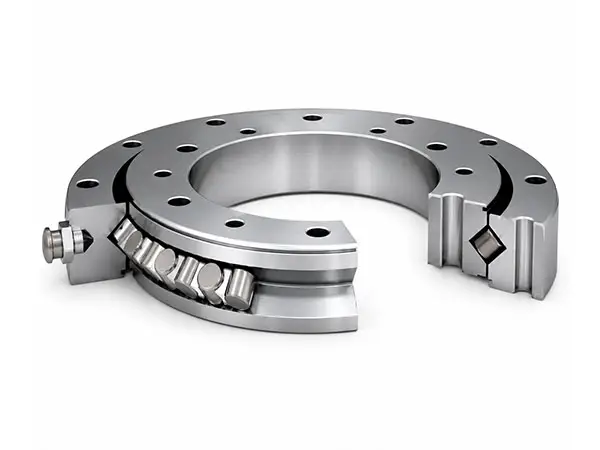
Alternating cylindrical rollers are arranged crosswise at 1:1. A single compact bearing can therefore carry axial load, radial load and overturning moment while maintaining high rotational accuracy.
Structure & Working Principle
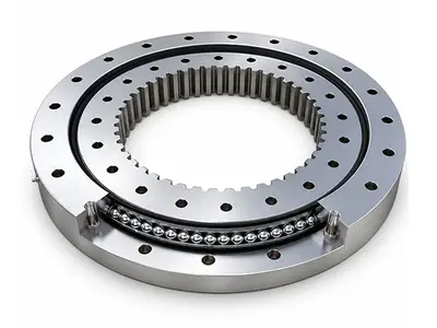
A Series 11 crossed roller slewing bearing is composed of two seat rings. Cylindrical rollers are alternately arranged at right angles and separated by spacers, so adjacent rollers transmit load in opposite directions. The compact arrangement provides high stiffness, small assembly clearance and precise rotational guidance.
The crossed roller geometry supports axial load, overturning moment and relatively high radial load at one bearing position. Compared with heavier multi-row designs, it offers a smaller cross-section and lower mass where installation space and positioning accuracy are important.
Performance profile
Compact structure
High stiffness
Small internal clearance
Combined-load capability
Precise rotation
Available Structural Versions
| Series | Gear version | Selection point |
|---|---|---|
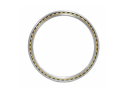
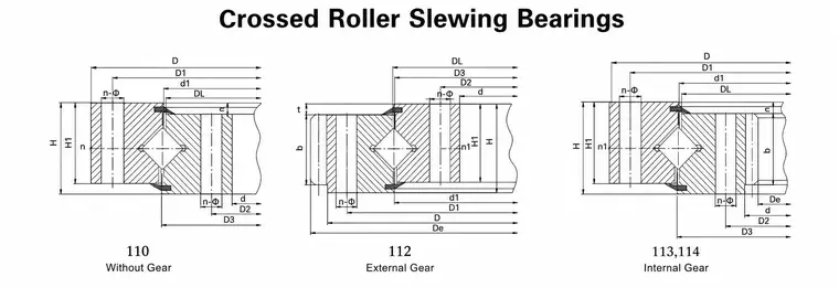
| 110 | Gearless | For systems with a separate drive mechanism or no integral ring gear. |
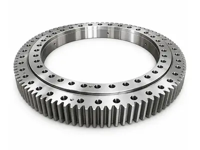
| 112 | External gear | Provides convenient pinion access, inspection and drive integration. |
| 113 / 114 | Internal gear | Provides compact, protected gearing with the pinion inside the bearing envelope. |
Key Features
One bearing position transmits radial, axial and overturning-moment loads.
Small clearance and rigid raceway support improve positioning repeatability.
The single crossed roller row reduces axial space and system mass.
Gearless, external-gear and internal-gear versions support different drive layouts.
Typical Applications
Hoisting equipment, transport machinery, construction machinery, industrial turntables, military equipment and other systems requiring compact combined-load support and accurate rotation.
Standard Product Range
| Parameter | Catalog range | Notes |
|---|---|---|
| Bore diameter d | 124.5–4,272 mm | Metric product range |
| Outside diameter D | 234–4,940 mm | Boundary outside diameter |
| Overall height H | 35–300 mm | Depends on ring and raceway design |
| Reference mass | 6.53–8,954 kg | Varies with size and gear arrangement |
| Gear module m | 2–30 mm | Applies to geared versions |
| Number of teeth z | 63–632 | Applies to geared versions |
| Gear face width b | 16–220 mm | Project-specific values available |
Representative Model Examples
| Model | Gear | d | D | H | m | z | b | Mass |
|---|---|---|---|---|---|---|---|---|
| D797/124.5G2 | Gearless | 124.5 | 234 | 35 | — | — | — | 6.53 |
| 111.12.260.03 | External | 200 | 322 | 35 | 2 | 165 | 16 | 11.2 |
| 2797/695G2 | Internal | 695 | 920 | 90 | 7 | 96 | 65 | 175 |
Key Features
Configuration & Dimensional Data
Available product data may include model, gear type, d, D, H, H1, h, lubrication-hole quantity, mounting-hole PCD and specifications, gear module, tip diameter, tooth count, face width, addendum modification and reference mass. Available items vary by model.
Design Selection Guide
Load case — define maximum axial load, radial load and overturning moment for operating, parked, emergency and transport conditions.
Gear arrangement — select gearless, external gear or internal gear according to drive layout, protection, inspection access and installation envelope.
Gear design — specify module, tooth count, pressure angle, quality, backlash, pinion data and duty spectrum; verify tooth-root and flank strength.
Mounting interface — confirm support stiffness, flatness, bolt grade, tightening method and hole arrangement. Through holes or tapped holes can be engineered.
Lubrication and sealing — provide accessible, evenly distributed lubrication points and choose grease and seals for the environment and temperature.
Catalog Engineering Notes
| Item | Guidance |
|---|---|
| Lubrication holes n1 | Lubrication holes are evenly distributed. Standard catalog grease fittings may use M10×1 interfaces to JB/T 7940.1–7940.2; project drawings govern. |
| Mounting holes | Inner- and outer-ring holes may be supplied as through holes or threaded holes according to the joint design. |
| Gear force | Where maximum pitch-circle tangential force is listed, nominal tangential force is typically one half; confirm by calculation for the selected model. |
| Internal-gear correction | Some standard internal-gear designs use an addendum modification coefficient of 0.2. The approved drawing defines the actual value. |
Information Required for Quotation
| Category | Please provide |
|---|---|
| Loads | Axial, radial and overturning-moment loads; load spectrum and safety factors. |
| Dimensions | Required d, D and H; installation envelope and support-ring dimensions. |
| Drive | Gear type, module, teeth, pinion, ratio, backlash and torque. |
| Operation | Speed, duty cycle, acceleration, shock, temperature and contamination. |
| Interfaces | Bolt-hole pattern, bolt grade, lubrication ports, seals and coatings. |
Typical Application Areas
| Application | Why Series 11 fits |
|---|---|
| Hoisting and crane equipment | Carries combined axial, radial and overturning-moment loads in a compact rotating joint. |
| Transport and construction machinery | Low cross-section and high stiffness support precise, durable rotation. |
| Industrial turntables and manipulators | Small clearance supports repeatable positioning and stable motion. |
| Special and military equipment | Multiple gear options simplify integration with different drive layouts. |
Available Models & Specifications
Click on any part number to view detailed CAD drawings and download PDF specifications.