Four-Point Contact Ball Slewing Bearings
One bearing position carries axial load, radial load and overturning moment, with gearless, external-gear and internal-gear configurations available.
Four-Point Contact Ball Slewing Bearings Overview
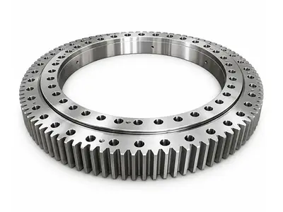
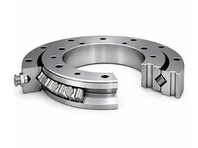
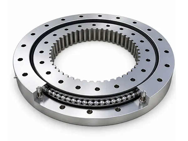
A Series 01 single-row four-point contact ball slewing bearing consists of two rings. Its compact, lightweight structure uses balls contacting the gothic-arch raceways at four points, allowing one bearing position to carry axial load, radial load and overturning moment simultaneously.
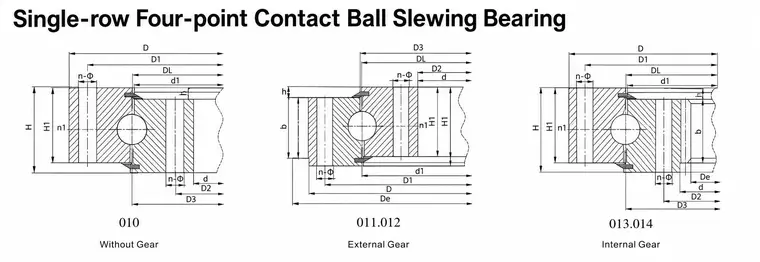
010 Series
Gear arrangement: Without gear
Recommended integration: Independent drive or external transmission
011, 012 Series
Gear arrangement: External gear
Recommended integration: Direct meshing with a pinion
013, 014 Series
Gear arrangement: Internal gear
Recommended integration: Compact enclosed transmission
Core advantages
Combined-load capability in a single compact bearing position
High structural rigidity with simplified mounting and maintenance
Flexible gear interfaces for different drive layouts
Typical applications
Slewing conveyors, welding manipulators, light- and medium-duty cranes, excavators and other construction machinery.
The calibrated product table covers metric and selected imperial designs. The values below describe the verified catalog scope; final capacity, gear data, mounting details and tolerances must be confirmed against the selected part number.
Technical Specifications
| Parameter | Verified range | Notes |
|---|---|---|
| Bearing type | Series 01 single-row four-point contact | Combined-load slewing bearing |
| Gear type | Gearless, external, internal | 010; 011/012; 013/014 |
| Inner diameter d | 83–4810 mm | Nominal value |
| Outer diameter D | 160–5277 mm | Nominal value |
| Overall height H | 20–279.4 mm | Calibrated field |
| Ring height H1 | 5–195 mm | Positive verified values |
| Height difference h | h = H − H1 | Used where applicable |
| Reference mass | 2.05–6220 kg | Reference only |
Representative models
| Model | Gear | d | D | H | H1 / h | kg |
|---|---|---|---|---|---|---|
| 010.20.228.03K | Gearless | 135 | 320 | 52 | 47 / 5 | 16.8 |
| 010.20.200.12 | Gearless | 156 | 256 | 60 | 50 / 10 | 11.5 |
| 011.08.121.03 | External | 83 | 160 | 25 | 20 / 5 | 2.05 |
| 011.08.180.03 | External | 136 | 222 | 25 | 18 / 7 | 2.96 |
| 013.20.310.12 | Internal | 235 | 380 | 54 | 44 / 10 | 25.6 |
| 013.30.560.03 | Internal | 444 | 662 | 80 | 70 / 10 | 91.1 |
SELECTION & ENGINEERING
Select the bearing by the combined axial load, radial load and overturning moment, then verify bolt-circle dimensions, mounting stiffness, permissible deformation, gear interface and lubrication arrangement. The supporting structure should be rigid and accurately machined to maintain load distribution around the raceway.
SELECTION & ENGINEERING
| Engineering item | Catalog guidance |
|---|---|
| Lubrication holes n1 | Evenly distributed; standard M10×1 grease fittings per JB/T 7940.1–7940.2. Position may be adjusted for the application. |
| Mounting holes | Through-holes or tapped holes are available; for tapped holes, the catalog basis uses diameter M and depth 2M. |
| Gear force | Listed tangential tooth force is the maximum value; nominal tangential tooth force is taken as one half. |
| Gear correction | Addendum modification is applied where specified; the internal-gear correction coefficient is 0.2 in the catalog basis. |
Inquiry checklist
| Required information | What to provide |
|---|---|
| Loads | Axial, radial and overturning moment; duty cycle |
| Envelope | Required d, D, H and mounting-hole layout |
| Drive | Gearless, external or internal gear; module and mating pinion |
| Operation | Speed, rotation angle, shock, temperature and environment |
| Lubrication | Grease type, relubrication interval and port position |
Available Models & Specifications
Click on any part number to view detailed CAD drawings and download PDF specifications.