
Three-row Cylindrical Roller Slewing Bearings
Three independent roller rows carry axial load, radial load and overturning moment through dedicated raceways—delivering exceptional load capacity and structural rigidity in large-diameter machinery.
Structure & Working Principle
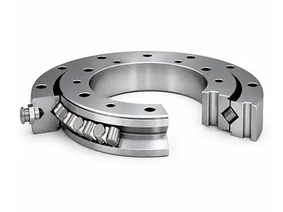
The three-row cylindrical roller slewing bearing consists of three bearing rings with the upper axial raceway, lower axial raceway and radial raceway separated from one another. Two horizontal roller rows primarily transmit axial loads and overturning moments, while the vertical roller row mainly carries radial load and guides rotation.
Because each load component is supported by a dedicated roller row, the load path can be defined accurately and the bearing achieves very high capacity, stiffness and operational stability. The design is especially suitable where installation space is available for a large, rigid bearing section.
Available Structural Versions
| Series | Gear version | Customer-facing selection point |
|---|---|---|
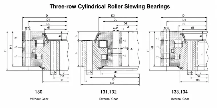
| 130 | Gearless | For systems driven by a separate mechanism or without an integral ring gear |
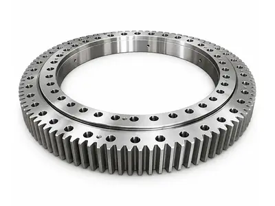
| 131 / 132 | External gear | Easy access for pinion drive and inspection |
| 133 / 134 | Internal gear | Compact protected gearing with the pinion inside the bearing envelope |
Catalog Range
| Parameter | Catalog range | Notes |
|---|---|---|
| Bearing type | Three-row cylindrical roller slewing bearing | Metric, application-engineered |
| Bore diameter d | 576–5230 mm | Across current CHG product table |
| Outside diameter D | 844–5940 mm | Gear tip diameter may differ |
| Overall height H | 125–430 mm | Dependent on ring and raceway design |
| Reference mass | 290–16,722 kg | Varies with size and gear arrangement |
| Gear module m | External: 6–28; Internal: 14–25.4 | Gearless versions omit m |
| Number of teeth z | External: 108–270; Internal: 89–219 | Final drawing governs |
| Gear width b | External: 80–270 mm; Internal: 107–266.7 mm | Can be project-specific |
| Lubrication & sealing | Distributed grease ports; integral seals | Port thread and seal material by design |
Design Selection Guide
- Load case — define maximum axial load, radial load and overturning moment, including operating, parked, emergency and transport conditions.
- Gear arrangement — select gearless, external gear or internal gear according to drive layout, protection, inspection access and available envelope.
- Gear design — specify module, tooth count, pressure angle, gear quality, backlash, pinion data and duty spectrum; verify tooth-root and tooth-flank strength.
- Mounting interface — confirm support stiffness, flatness, bolt grade, tightening method and hole arrangement. Through holes or threaded holes can be engineered.
- Lubrication & sealing — provide accessible, evenly distributed lubrication points and choose grease and sealing materials for the environment and temperature.
Catalog Engineering Notes
| Item | Guidance |
|---|---|
| Lubrication holes n1 | Lubrication holes n1 are evenly distributed; the corrected catalog lists the applicable quantity for each model. Lubrication-port thread and interface are model-specific and shall follow the current parameter table and approved drawing |
| Mounting holes | The corrected catalog identifies the outer- and inner-ring mounting-hole pitch-circle diameters as D1 and D2. Hole quantities and through-hole/threaded specifications are model-specific; project drawings govern. |
| Gear force | Where a table lists maximum pitch-circle tangential force, the catalog rated tangential force is typically taken as one half; confirm against the selected model calculation. |
| Internal-gear correction | Some standard Series 13 internal-gear designs use an addendum modification coefficient of 0.2; the workbook and approved drawing define the actual value. |
Typical Applications
Bucket-wheel excavators
Crawler & mobile cranes
Ship & harbor cranes
Ladle turrets and steelmaking equipment
Tunnel boring machines
Direct-drive wind turbine main shafts
Information Required for Quotation
| Category | Please provide |
|---|---|
| Loads | Axial, radial and overturning moment loads; load spectrum and safety factors |
| Dimensions | Required d, D and H; available installation envelope and support-ring dimensions |
| Drive | Gearless/external/internal gear; module, teeth, pinion, ratio, backlash and torque |
| Operation | Speed, duty cycle, acceleration, shock, temperature, contamination and corrosion |
| Interfaces | Bolt-hole pattern, bolt grade, lubrication ports, seals and special coatings |
| Life & standards | Required service life, inspection criteria, certification and traceability requirements |
Available Models & Specifications
Click on any part number to view detailed CAD drawings and download PDF specifications.