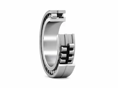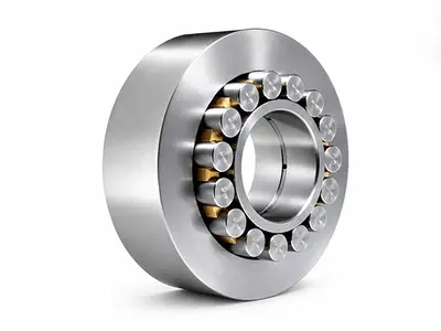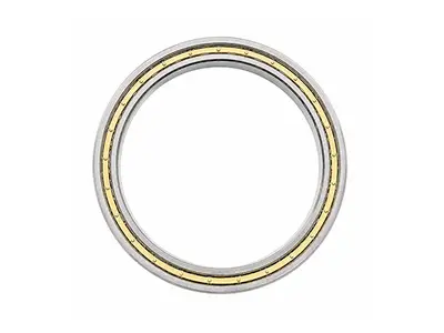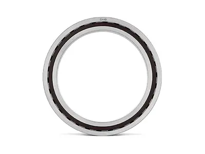
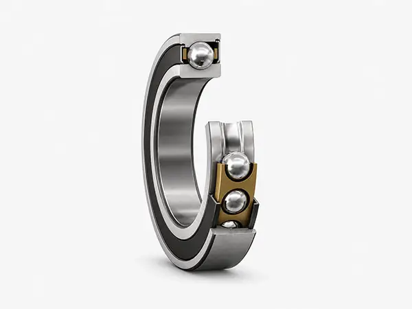
Super-precision Angular Contact Ball Bearings
CHG super-precision angular contact ball bearings are engineered for machine-tool spindles and other demanding rotating systems that require high running accuracy, high speed capability, controlled rigidity, low friction and stable thermal behavior.
Key Parameters
| Product family | Super-precision angular contact ball bearings |
|---|---|
| Dimensional series | 718, 719, 70 and 72 series; availability depends on design and size |
| Contact angle | 15° and 25° standard design options; 18° for selected requirements after review |
| Supply format | Single, universally matchable, matched pairs or multi-bearing sets |
| Typical applications | Machine-tool spindles, grinding, milling, turning, high-speed motors and precision test equipment |
Super-precision Angular Contact Ball Bearings Overview
Super-precision angular contact ball bearings have asymmetrical raceways. The contact angle enables the bearing to carry radial load together with axial load in one direction. In spindle systems they are normally adjusted against a second bearing, or supplied as a matched set, to locate the shaft in both directions and establish the required preload.
Key Features and Customer Benefits
- High running accuracy supports stable tool-point position, surface finish and dimensional consistency.
- Optimized internal geometry and cage design support high-speed operation with low friction and reduced heat generation.
- Multiple contact angles and preload levels allow the speed-rigidity-load balance to be tuned for the application.
- Universally matchable and matched-set options simplify assembly and improve load sharing across bearing groups.
- Steel-ball and hybrid ceramic-ball designs address different speed, inertia, wear and thermal requirements.
- Open, sealed and oil-air lubrication-ready solutions can be reviewed according to series and operating conditions.
Product Series Selection
| Series | Cross section | Speed potential | Load & rigidity | Typical selection |
|---|---|---|---|---|
| 718 | Ultra-light | Very high | Moderate, compact | Minimum envelope, measuring systems, compact precision spindles |
| 719 | Extra-light | Very high | Balanced | High-speed grinding and motorized spindles |
| 70 | Light | High | Higher capacity and rigidity | General high-performance machine-tool spindles |
| 72 | Medium | Moderate to high | High capacity and rigidity | Heavy-duty precision spindles and high system stiffness |
Contact Angle and Performance Balance
Contact angle is measured between the line joining the ball-raceway contact points and a plane perpendicular to the bearing axis. A smaller angle generally favors speed; a larger angle generally increases axial capacity and axial rigidity. The final choice must also consider preload, bearing size, lubrication and operating temperature.
Contact Angle and Performance Balance
| Contact angle | Speed | Axial capacity & rigidity | Typical use |
|---|---|---|---|
| 15° | Highest potential | Lower than larger angles | Very high-speed spindles |
| 18° | High | Intermediate | Selected speed-rigidity balance |
| 25° | High to moderate | Higher | Higher axial load and stiffness |
Engineering Note
A contact angle must not be selected in isolation. Increasing preload or contact angle can improve rigidity, but it also raises friction and heat. Validate the complete spindle system under the actual speed, load, lubrication and cooling conditions.
Single-row angular contact ball bearings are normally used in pairs or sets. Arrangement determines axial load direction, moment stiffness, thermal response and the effective spread between pressure centers.
Bearing Arrangements
| Arrangement | Axial load | Characteristic | Recommended use |
|---|---|---|---|
| Back-to-back DB (O) | Both directions | Wide pressure-center spread; high moment rigidity | Most rigid spindle locating position |
| Face-to-face DF (X) | Both directions | Narrower spread; more tolerant of some misalignment | Applications with alignment or thermal considerations |
| Tandem DT | One direction | Shares axial load in one direction | High one-direction thrust; combine with opposed bearing(s) |
| Multi-bearing set | Application-specific | Combines rigidity, capacity and thermal design | High-performance spindle cartridges |
Precision, Matching and Preload
Super-precision bearings are controlled not only by boundary-dimension tolerances, but also by running accuracy and matching characteristics. CHG can review P4A-equivalent or higher precision requirements, depending on size, design and inspection agreement. Final tolerances shall be stated on the approved drawing or technical specification.
Precision
Boundary dimensions, radial/axial runout and raceway accuracy are controlled for spindle performance
Universal matching
Bearings can be mounted in specified DB, DF or DT combinations without individual pair selection when supplied for universal matching
Matched sets
Two, three or four bearings can be supplied as an identified set for controlled preload and load sharing
Preload
Light, medium, heavy or application-specific preload is selected according to speed, rigidity, load and thermal conditions
Materials, Cages, Sealing and Lubricatio
Rolling elements: Bearing steel balls or silicon-nitride ceramic balls in hybrid designs
Bearing rings: High-quality bearing steel; special materials subject to engineering review
Cage: High-speed polymer/phenolic or other engineered cage according to series and temperature
Sealing: Open or sealed design where available; seal friction and speed limits must be considered
Lubrication: Grease, oil-air or other precision lubrication selected by speed factor, load, heat removal and service strategy
Hybrid Ceramic Bearing Advantages
- Lower ball mass reduces centrifugal force at high speed.
- Higher elastic modulus can improve contact stiffness under comparable conditions.
- Reduced adhesive wear risk and favorable tribological behavior can support demanding lubrication conditions.
- Electrical insulation through ceramic balls can help reduce current passage damage in motorized spindles.
- Hybrid design does not automatically increase the permissible speed of every spindle. Ring fits, preload, cage, lubrication, rotor balance and cooling remain decisive.
Application Areas
High-speed machining centers and motorized spindles
Grinding, milling, turning and boring spindles
Precision high-speed motors and test rigs
PCB drilling, woodworking and engraving spindles
Robotics, measuring systems and precision rotary equipment
Turbo machinery, dynamometers and other application-specific high-speed units
Selection Workflow
Define the shaft size, available envelope and target dimensional series.
Provide radial load, axial load, moment, load direction and duty cycle.
Set maximum speed, acceleration, target life and acceptable temperature rise.
Choose contact angle and arrangement according to speed, axial load and moment rigidity.
Select precision, preload, steel/hybrid design, cage, seals and lubrication.
Verify shaft/housing fits, shoulder geometry, clamping method, cooling and assembly process.
Confirm the final designation, drawing, inspection plan and acceptance criteria.
Installation and Operating Guidelines
Keep bearings, tools and assembly areas exceptionally clean; small contamination can impair spindle accuracy and life.
Apply mounting force only to the fitted ring. Never transmit mounting force through the balls.
Control shaft and housing roundness, coaxiality, shoulder squareness and clamping-face parallelism.
Do not mix bearings from identified matched sets; preserve orientation and sequence markings.
Meter grease quantity carefully or validate the oil-air delivery rate. Excess lubricant can cause heat and speed instability.
Use a controlled run-in procedure and monitor temperature, vibration, noise and drive power.
Do not use catalogue speed as the spindle speed limi
Permissible spindle speed depends on bearing size and design, preload, arrangement, fits, lubrication, cooling, load, rotor balance and required life. Final speed capability requires system-level verification.
Customization and Engineering Support
Non-standard dimensions, ring geometry and interface features
Precision level, preload and matched-set configuration
Steel-ball or hybrid ceramic-ball construction
Open, sealed and lubrication-specific variants
Application calculation, drawing review, inspection reports and traceability documents
CHG Bearing provides application engineering and customized bearing development from Luoyang. Our engineers can review the complete spindle arrangement before quotation and support prototype validation through batch production.
Information Required for Quotation
Bearing designation or d × D × B dimensions and dimensional series
Spindle arrangement drawing and shaft/housing fits
Maximum and continuous speed, acceleration and duty cycle
Radial load, axial load, moment and load direction
Required accuracy, runout, rigidity, preload and target life
Lubrication, cooling, temperature, contamination and electrical conditions
Quantity, destination country, certificates and delivery date
Available Models & Specifications
Click on any part number to view detailed CAD drawings and download PDF specifications.